Magnetic Field Simulation of DBS Electrodes
 |
Lena JaschkeProject duration: March 2016 - September 2016The project was supported by the program for promotion of excellent women in science by the Faculty of Engineering / Christian-Albrechts-Universität zu Kiel. |
|---|
Abstract
A new type of magnetoelectric sensor — that is developed within the Collaborative Research Center 1261 (CRC 1261) at Kiel University — are proprosed to open up new possibilities in the field of medical measuring. In contrast to conventional magnetoelectric measuring techniques this sensors are capable to operate at normal conditions. [1] In connection with therapies such as Deep Brain Stimulation (DBS) the sensors can enable a new way to estimate the position of the implanted DBS electrodes. In this article, we focus on the estimation of the resulting magnetic field around a head phantom caused by a transplanted DBS electrode in order to be able to localize in a further step the electrode in the brain given measured data.
Introduction
Whereas currently used measurement systems such as SQUID sensors require a cryogenic operating environment [2], the new type of magnetoelectric sensor — that is developed wihtin the Collaborative Research Centre 1261 (CRC 1261) at Kiel University — represents a cheap alternative for the detection and measurement of extremely subtle magnetic fields, e.g. the brain’s magnetic field, under normal conditions. Neither external magnetic bias fields nor cooling are required. This leads to the possibility of the broader medical use of this technique, e.g. for diagnosing numerous conditions such as epilepsy and dementia [1]. Furthermore it will open the possibility to improve therapies such as deep brain stimulation (DBS) for treating Parkinson’s disease. After a short introduction of the DBS and it’s single components, this article will focus on the estimation of the resulting magnetic field around the head phantom caused by a transplanted DBS electrode in the brain.
Deep Brain Stimulation
![Fig. 1. Components of the deep brain stimulation [4].](/images/teaching/projects/dbs_field_simulation/dbscomponents.jpg) |
|
Fig. 1. Components of the deep brain stimulation [4]. |
DBS is a promising neurosurgical procedure for the treatment of movement and neuropsychiatric disorders [3]. A general overview of the individual components of the DBS is given in Fig. 1.
The DBS system consists of three separate components: a neurostimulator, the DBS lead with four cylindrical contacts at one end, and an extension cable that connects those two components. As illustrated in Fig. 1 the neurostimulator gets placed under the skin of the chest below the collarbone or in the abdomen of the patient. The electrodes, that are placed in a specific area of the brain (usually in the subthalamic nucleus) are connected to the stimulator device via extension wires, that are passed under the skin from the scalp, behind the ear, down the neck, and to the chest.
Neurostimulator
The considered neurostimulator (Medtronic Activa SC Model 37602, [5]) represents a multi-program battery-powered pacemaker device that creates electric pulses. After the operation the stimulation parameters like pulse shape, frequency and amperage for DBS get customized for each patient in a way that the stimulation leads to the best treatment success without side effects.
An important stimulation parameter constitutes the frequency. Depending on the frequency one disinguish between the high- and the low-frequency DBS. High-frequency DBS is used for the treatment of Parkinson’s disease, tremor and dystonia with a frequency in the range of 100 to 185 Hz (usually approx. 130 Hz) [6]. However for the low-frequency stimulation, which got tested for the treatment of epilepsy, frequencies in the range of 10 to 40 Hz were applied [7].
The pulse shape, that is defined by the pulse width and the amplitude, represents beside the frequency another important stimulation parameter. Conventionally individual rectangular pulses were used in the DBS. For the treatment of Parkinson’s disease usually a pulse width of 60 \( \mu s \) is set. In some exceptions the pulse width can be extended to 90 or 120 \( \mu s \) [6]. For the treatment of psychiatric disorders the set pulse width for DBS lies in the range of 60 up to 450 \( \mu s \) [7]. The pulse width determines the neuronal elements, that get excited: while high pulse widths affect the cell soma, shorter pulse widths mainly influence the axons [7].
A parameter that has to be determined for each patient individually constitutes the amperage [7]. It has to be set in a way, that the effect of DBS in combination with the medication show an optimal result without the occurance of undesired side effects. The current can be adjusted in a range between 0 and 25.5 mA. By reasons, described in [8], in our model the voltage is set to 191 \( \mu A \).
 |
|
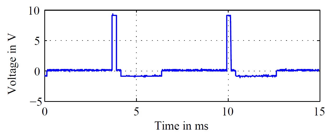
Fig. 2. Emulated stimulation signal of the pacemaker with f = 160 Hz. |
The considered neurostimulator generates biphasic impulses as ordinarily for clinical used DBS stimulators. The measured stimulation impulse, that forms the basis for the further investigations is illustrated in Fig. 2 for a frequency of f = 160 Hz.
An adjustment of the stimulation settings can be done in the case, that the patient’s condition changes over time. Furthermore usually intermittent stimulation is used — a gap in between the stimulation process can be used for a resensitization of the nervous system, in order to reach again good results with a small stimulation amplitude [6].
DBS extensions and leads
The neurostimulator is connected via an extension cable (Medtronic Model 7483 DBS Extension Kit, [9]) with the DBS lead (Medtronic Model 3389 DBS Lead, [10]).
The extensions and implantable leads do not contain any active, electronic components. As depicted in Fig. 3 four cylindrical, platinum-iridium contacts at the distal end of the leads are interconnected by four non-interlacing, spiral wound, fluropolymer-insulated platinum-iridium wires to four cylindrical, nickel alloy contacts at the other end. While the contacts at the distal tip interface with neural tissue, the contacts at the proximal end of the lead serve as the connection point between the lead and the distal aspect of the extension cable [11]. The four contacts can be switched on and out separately for the DBS.
 |
|
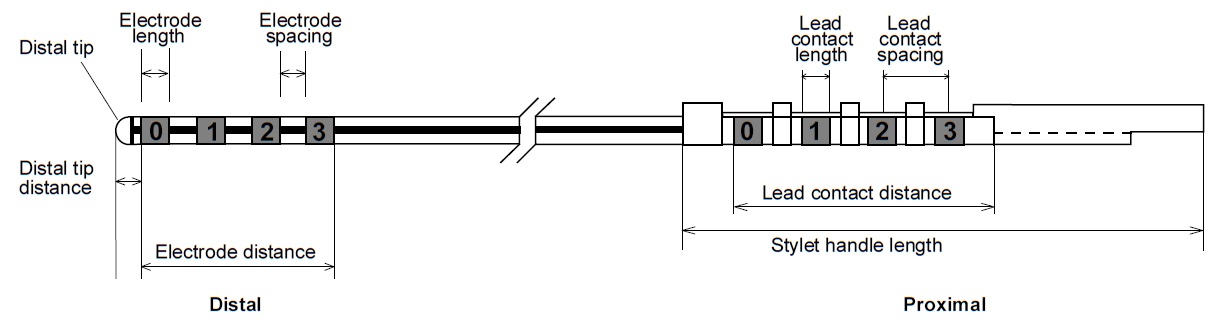
Fig. 3. Electrode, lead contact, and stylet [10]. |
Depending on the application, different lead models were used. The considered model (Model 3389), has contacts that are 1.5 mm in length with a 0.5 mm electrode spacing. Thus a electrode distance of 7.5 mm is obtained. The considered cylindrical contacts are 1.27 mm in diameter [10].
DBS Magnetic Field
An advantage of biomagnetic signals against bioelectric signals consists in the almost not existing distortion of the magnetic field in tissue. By virtue of a practically constant permeability of \( \mu_{r} \) = 1, the human body can be seen as approximately magnetically transparent [12]. Therefore a more precise localization is enabled.
The measurable magnetic field around the head of a patient depends primarily on the stimulation method. In the case of unipolar stimulation only one electrode is active and the shell of the neurostimulator — placed in the thorax of the patient — serves as counter electrode in order to close the current cycle. However applying a bipolar stimulation mode leads us to a current flow between two or more contacts of the electrode.
Due to the twisted cable configuration, in the bipolar mode a cancelation of the magnetic fields of the forward and returning current flow can be observed. Therefore measurements show a 100 times higher magnetic field for the unipolar stimulation mode [13].
The detailed examination of this two different configurations will be described in the following sections.
Bipolar mode
![Fig. 4. Bipolar configuration of the DBS electrode [13].](/images/teaching/projects/dbs_field_simulation/bipolar.jpg) |
|
Fig. 4. Bipolar configuration of the DBS electrode [13]. |
During normal operation, pulsed electrical current is passed from the neurostimulator through the extension lead to the neural tissue [11]. As already mentioned within the bipolar mode two or more contacts of the electrode get interconnected in a way, that a current flow between them arises as displayed in Fig. 4. Thus in the bipolar case the anode is represented by one or more additional contacts at the distal tip of the lead [11].
The forward and the returning current flow in the wire lead to a strong reduction of the corresponding magnetic fields. In the following the assumption is made, that the magnetic field resulting by the forward current flow is completely canceled by the one arising from the returning current flow. Hence the magnetic field that is to be considered for the bipolar configuration originates from a magnetic dipole moment. Thus the magnetic field for the bipolar mode arises, considering the lead model 3389, from the current flow over a distance of at most 7.5 mm.
Unipolar mode
 |
|
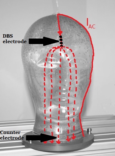
Fig. 5. Unipolar configuration of the DBS electrode. |
In the case of a unipolar stimulation, again pulsed electrical current is passed from the neurostimulator through the extension lead to the neural tissue. However the anode in order to close the current cicle in this configuration is represented through the metal case of the neurostimulator which is placed in the thorax of the patient.
For investigations on the head phantom, a counter electrode from stainless steel is placed in the neck of the phantom as illustrated in Fig. 5.
The measurable magnetic field around the head phantom in this case consists of field components caused by the flow of electric charge through the wire from the neurostimulator to the electrodes and the current flow through the neural tissue from the electrode to the counter electrode. The rough schematic of the current cicle is displayed in Fig. 5.
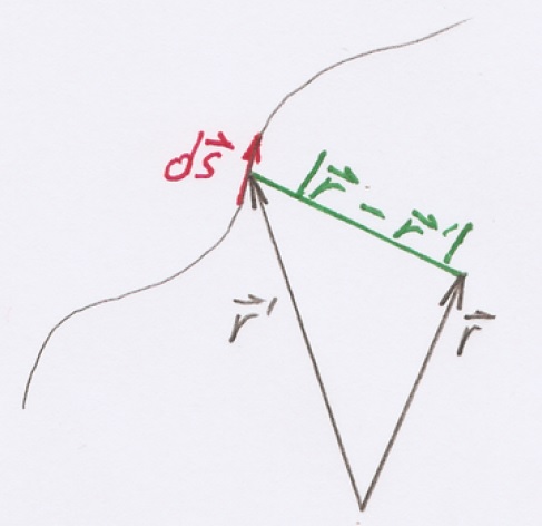
The resulting magnetic field for the current depicted in Fig. 5 with a solid line, can be calculated using the Biot-Savart law. For the case of a line-shaped conductor the magnetic flux density \( \vec{B} \) can be calculated by the Biot-Savart law by:
\begin{equation} \vec{B}(\vec{r}) = \frac{\mu I}{4 \pi} \int\limits_{C} \frac{d \vec{s'} \times (\vec{r}-\vec{r'})}{| \vec{r}-\vec{r'} |^3}\end{equation}
 |
|
Fig. 6. Components of the Biot-Savart law. |
The vector \( \vec{r} \) defines the measurement location, while \( \vec{r'} \) specifies the location of the source. In turn \( I \) is the current in ampere and \( \mu \) the permeability in vacuum (\( \mu_{0} = 4 \pi \times 10^{-7} N/A^2 \)). The single components of the Eq. 1 are illustrated in Fig. 6.
The components of the magnetic field get calculated for each point of the space separately and in the end additively superimposed.
While the magnetic field arising by the current flow through the wire can be calculated as proposed above, the law of Biot-Savart is not applicable for the calculation of the magnetic field for the current depicted in Fig. 5 with a dashed line. The flow of the electric charge from the electrode down to the counter electrode is divided into a whole bunch of different paths through the neural tissue. A proper determination of this field can be obtained with the assistance of an appropriate magnetic field simulation software.
Field Simulation
 |
|
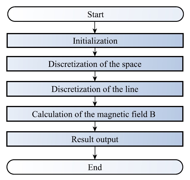
Fig. 7. Schematic of the program for the magnetic field simulation. |
The simulation of the magnetic field around the DBS electrode got implemented using MATLAB. An overview over the individual steps of the program is illustrated in Fig. 7.
Within the initalization step, global parameters, as the permeability in vacuum \( \mu_0 \) get set. After an appropriate discretization of the space, the ’active’ part of the line — depending on the choosen stimulation mode — gets discretized as well. ’Active’ in this case refers to the flow of considerable electric charge. In a further step the magnetic field components get calculated using the Biot-Savart law for each point of the space separately and in the end additively superimposed.
The two following videos illustrate the simulated magnetic field for the unipolar as well as for the bipolar configuration.
Conclusion and Outlook
This document is concerned with the estimation of the magnetic field around the head phantom, caused by a transplanted DBS electrode in the brain. Therefore the deep brain stimulation, it’s components and parameters and the two different stimulation modes were presented and analyzed. Parts of the magnetic fields were simulated using MATLAB. However, to capture the holistic scope of the resulting magnetic field, the utilization of a magnetic field simulation software will be requiered in further studies.
Once the magnetic field is estimated in a proper fashion, the results in combination with measured data can be used in order to apply an localization algorithm on the model and determine the position of the implanted DBS electrode. Out of the determined electrode position valuable information about the functionality could be extracted.
By the fact, that DBS commonly is performed on both sides of the brain, because each side of the body gets controlled by one side of the brain, the contemplation of the magnetic field caused by two individually operating stimulation electrodes represents an interesting field for further investigation.
References
| [1] | S. Maack, “Nano materials for medical measuring devices,” Online, April 2012, available: http://www.uni-kiel.de/ aktuell/pm/2012/2012-121-biomagnetische-sensoren-e.shtml [Accessed: May 2016]. | |
| [2] | J. G. Webster and H. Eren, Measurement, Instrumentation, and Sensors Handbook, Second Edition: Spatial, Mechanical, Thermal, and Radiation Measurement, 2nd ed. CRC Press, 2014. | |
| [3] | X. Zhong, Y. JT, Z. Q, W. ND, and T. L, “Deep brain stimulation for epilepsy in clinical practice and in animal models,” Brain Research Bulletin, vol. 85, pp. 81 – 88, 2011. | |
| [4] | Mayfield Clinic, “Deep brain stimulation for movement disorders,” Online, April 2016, available: http://www.mayfieldclinic. com/PE-DBS.htm [Accessed: July 2016]. | |
| [5] | Medtronic, Activa SC 37602 Multi-program neurostimulator. | |
| [6] | D. Kern and R. Kumar, “Deep brain stimulation,” The Neurologist, vol. 13, pp. 237–52, 2007. | |
| [7] | S. Kücker, “Basalganglien und Epilepsie: Elektrophysiologische Untersuchungen und experimentell-therapeutische Neurostimulation in Tiermodellen für die Temporallappenepilepsie,” Ph.D. dissertation, Tier¨arztliche Hochschule Hannover, 2009. | |
| [8] | S. Salzer, “Untersuchung der Anwendbarkeit von magnetoelektrischen Sensoren in biomagnetischen Messsystemen,” Master thesis, University Kiel, 2014. | |
| [9] | Medtronic, DBS Extension Kit for Deep Brain Stimulation Model 7483. | |
| [10] | Medtronic, DBS Lead kit for deep brain stimulation Model 3387, 3389. | |
| [11] | D. Tarsy, J. L. Vitek, P. A. Starr, and M. S. Okun, Deep Brain Stimulation in Neurological and Psychiatric Disorders, 1st ed. Humana Press, Springer Science and Business Media, 2008. | |
| [12] | University Dortmund, “Elektrische und magnetische Felder,” Online, available: https://e3.physik.uni-dortmund.de/suter/ Vorlesung/MedizinphysikII 13/16 ElektrischMagnetisch.pdf [Accessed: August 2016]. | |
| [13] | R. Jahns, “Untersuchung und Optimierung von Empfindlichkeit und Rauschverhalten magnetoelektrischer Sensoren,” Ph.D. dissertation, University Kiel, 2013. |
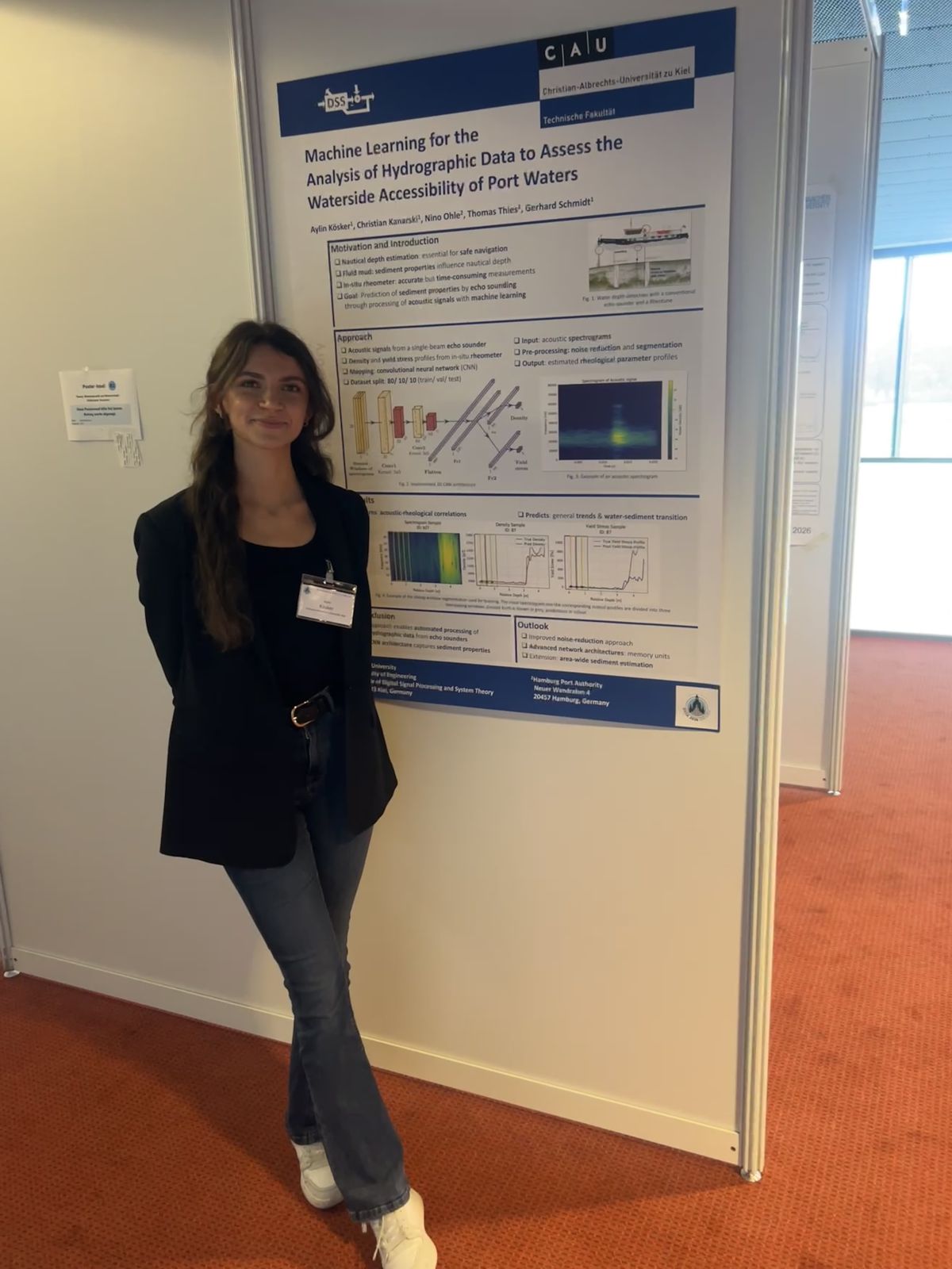 In March 2026, the DSS Chair attended the annual DAGA conference in Dresden. Thanks to the support of the GaS-Club, the student Aylin Kösker was given the opportunity to accompany the chair and participate in the conference from March 23rd to March 26th. As part of the daily poster sessions, she presented the results of her bachelor’s thesis “Machine Learning for the Analysis of Hydrographic Data to Assess the Waterside Accessibility of Port Waters” in the field of Underwater Acoustics. The thesis forms an important basis for an ongoing university research project on the acoustic analysis of sediment properties in harbor areas. The poster session enabled valuable discussions with researchers and conference participants from related research fields.