Electric Guitar Distortion
 |
||
| Contents: | ||
Electric guitar distortion is a traditional field of audio effects. In its simple form it means hard or soft clipping the signal. Clipping a signal is a form of signal distortion, in the context of audio effects sometimes also called overdrive. Overdrive or distortion will produce many strong harmonics. The distortion may be generated already before power amplification from an external effect pedal or inside the power amplifier (esp. with tube amplifier). Finally the already distorted and amplified signal is fed into loudspeakers installed in a cabinet. The loudspeaker(s) (incl. cabinet) may again distort the signal and also will introduce linear frequency range limitations and resonances (linear filtering). Resonances may result from guitar speaker itself and/or from the cabinet (open backside). Some more details can be found here.
 Discussing the details of electric guitar distortion is not possible within this script. As a first simple reference point for further literature we recommend to look inside Wikipedia, e.g. here (the link leads to the German wiki, the English version shows an ‘own’ content).
Many effect pedals are still analog. We will introduce a simplified installation with an external digital effect pedal, i.e. the effect pedal contains digital signal processing. After distortion we may add two filtering stages, a fist modelling the amplifier (non-linear filter) and a second modelling the speaker inside the cabinet. Power amplification is performed with a linear amplifier.
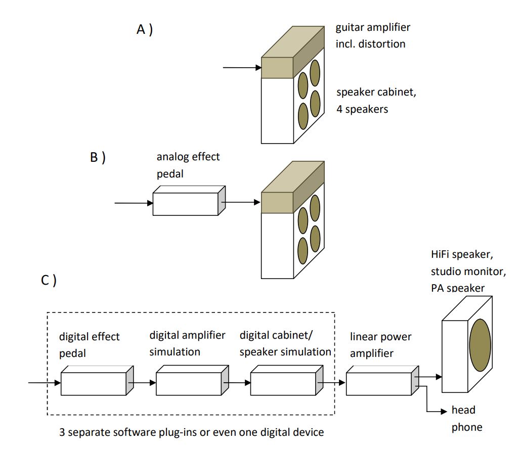
Following figure shows the classic "all in one" setup A) with the distortion included in the amplifier (usually a tube amplifier) and the amplifier often attached to the speaker cabinet. In the example we see a cabinet with 4 speakers. B) is a classic solution with an extra analog distortion pedal giving more sound possibilities compared to the ‘all in one’ solution. C) is the digital audio effect solution we are mainly interested in. Inside a digital audio workstation DAW one may have 3 separate software plug-ins for distortion, amplifier simulation and speaker cabinet simulation. An alternative solution is a separate digital device including all this software. Listening may be done with an acoustically ‘neutral’ studio monitor, head phones or a good quality HiFi speaker. For a stage performance a robust, powerful PA speaker may be used.
The company Roland® was the first successfully presenting a digital distortion simulation. Company Line 6® made the simulation approach popular (source: Wikipedia, Gitarrenverstärker). Other companies did follow. After some search we found a very simple, but flexible digital hardware solution from company Source Audio LLC with the name ‘Pro Classic Distortion’ of the series soundblox®. The user guide of this device says: ‘... features distortion effects that are re-creations of popular pedal and amplifier based distortions’.
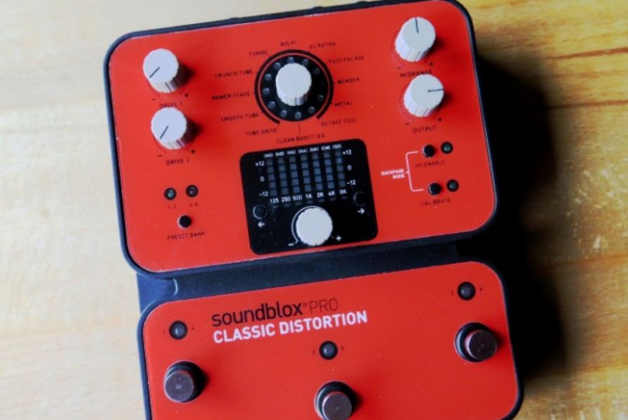 ‘Pro Classic Distortion’ is a digital device with a signal processor SA601 inside and 24bit signal converters. 11 different ‘classic’ distortion sounds are provided. The meaning of ‘classic’ is that it was tried to digitally simulate classic distortion sounds from famous amplifiers and/or effect pedals. The 11 types e.g. are named TUBE DRIVE, an overdrive tube amp sound similar to the famous Marshall® sound, or SMOOTH TUBE as a sound based on famous Mesa-Boogie® pre-amp distortion, or e.g. EL RATON based on the ProCo Rat®.
There is a 12th sound called Clean Boost/EQ first to provide a clean sound together with a 7 band equalizer and secondly together with the 2 DRIVE knobs to adjust a simple hard clipping of the signal.
In the user guide it s not explicitly said that a speaker cabinet simulation is included. It may be assumed, but it is not sure. As a substitute a included 7 band EQ may be used to introduce specific frequency band limitations and/or resonances. (At the end of this chapter we will give an example of a separate speaker cabinet simulation.)
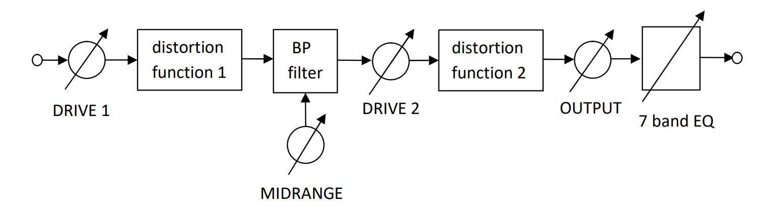 A schematic or block diagram of this device is not available. From the description in the user guide we deduced the following simplified block diagram.
The input levels of the 2 distortion blocks are controlled from the 2 drive knobs, a band pass BP is placed in between the distortion blocks. Please remember in the chapter about the non-linear exciter device we used 2 distortion blocks in parallel, here 2 blocks are in cascade form. The midrange knob adjusts the BP filter and thus additionally increases the sound possibilities. The BP delivers a 12 dB range of cut or boost to a midrange frequency band (bandwidth about 2 octaves).
There are many different distortion pedals and amplifier simulations from different companies (e.g. Boss, Ibaniz, Roland, Yamaha, Korg, Line 6, TC Helicon ...). The reason that we did introduce the soundblox Classic Distortion is that this device tries to implement many other famous sounds in one box and the reason that we believe that the cascade of to two distortion curves is an interesting flexible concept.
If the implemented sounds finally meet the taste of the musician is beyond our scope and also to look at further implementations details of the algorithms is not our intention and finally even is impossible.
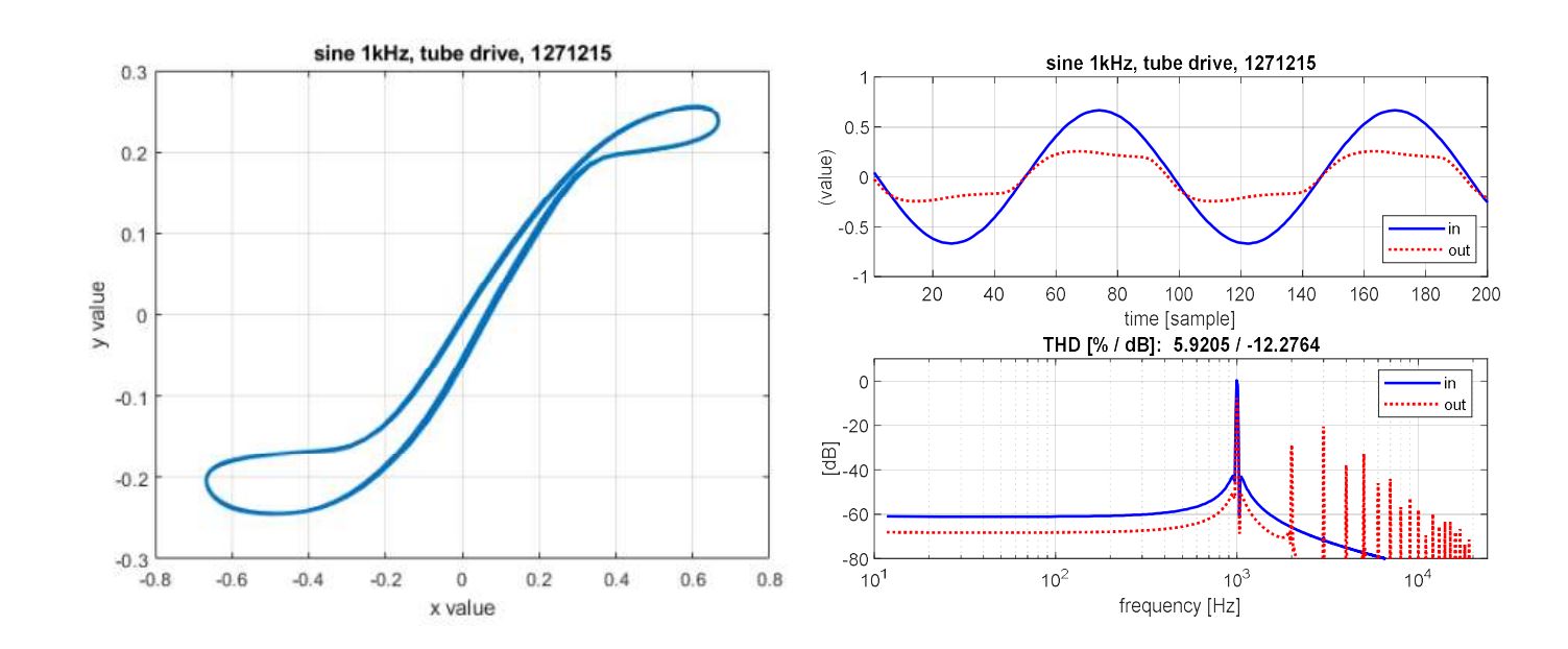
We will present a rough technical view for the non-linearity, i.e. showing some simple technical measurements of the distortion curves and the spectra of the distorted signals. We restrict to the Clean Boost and to the Tube Drive.
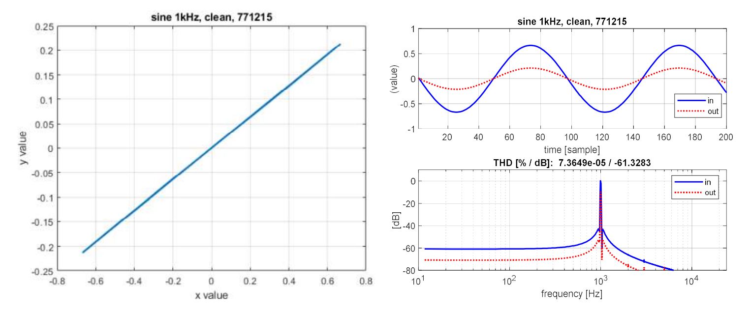
For input we use a sinusoid signal of 1kHz. Amplitude is -3dB FS, or physically ... Veff. For all figures we fixed MIDRANGE knob to 12 o’clock (setting to the middle value) and OUTPUT to 15 o’clock (giving some headroom, max is 17 o’clock). The 7 band EQ was not used. The audio interface used 96kHz sampling rate to allow an accurate post compensation of the phase (delay) between ‘in’ and ‘out’.
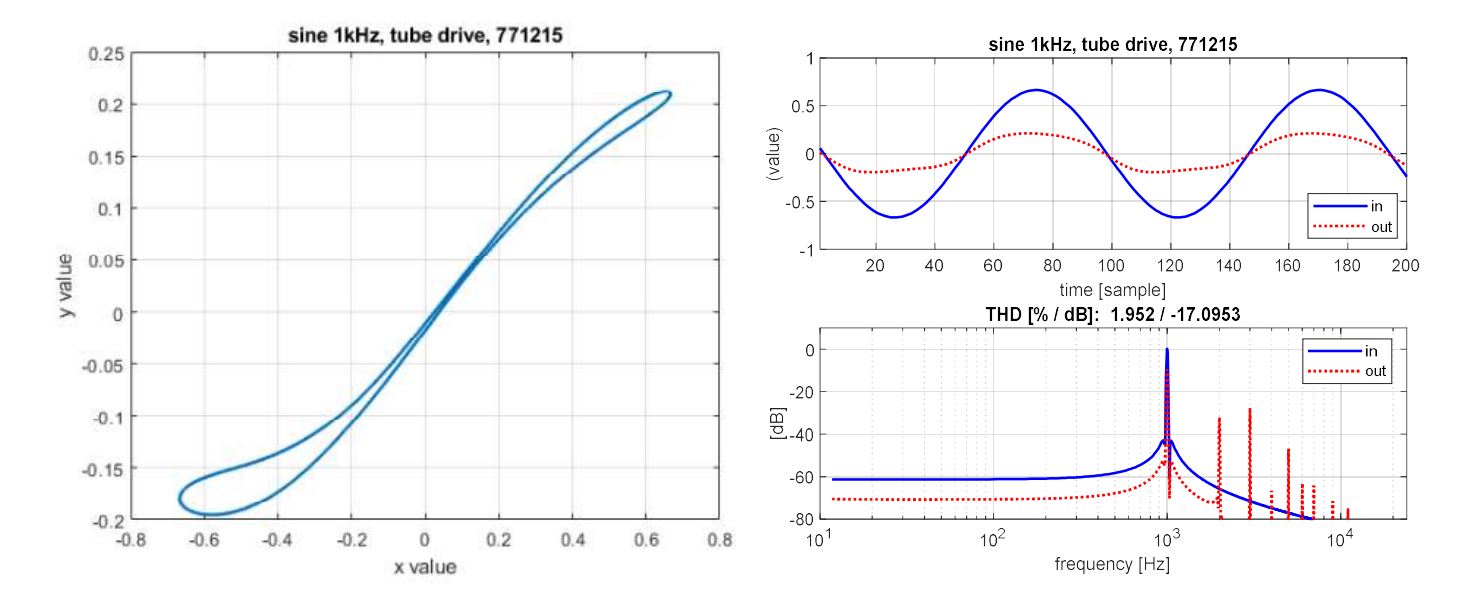
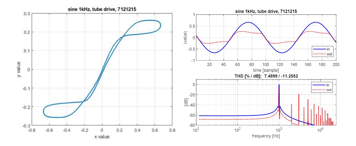
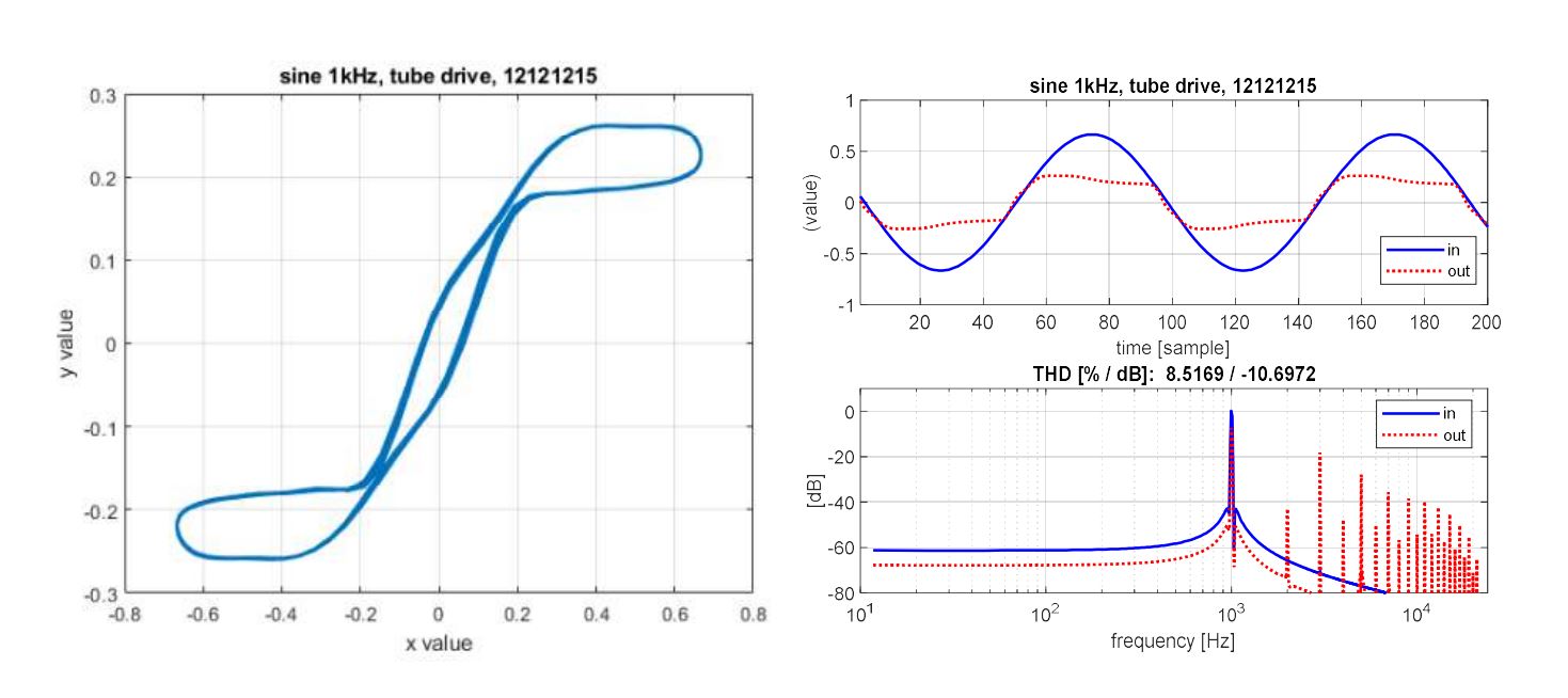
Note that we see a hysteresis of the in/out curve. This is a result of a non-linear phase, i.e. different frequencies arrive at different times, re-combining to an output signal shape different from the input shape. In our example we have a symmetric input shape, but see a non-symmetric output shape. A simple linear(!) recursive filter produces this result (applied after non-linear amplitude distortion).
Clean Boost
Drive1: 7 o’clock and drive2: 7 o’clock -> we are in the linear range
 |
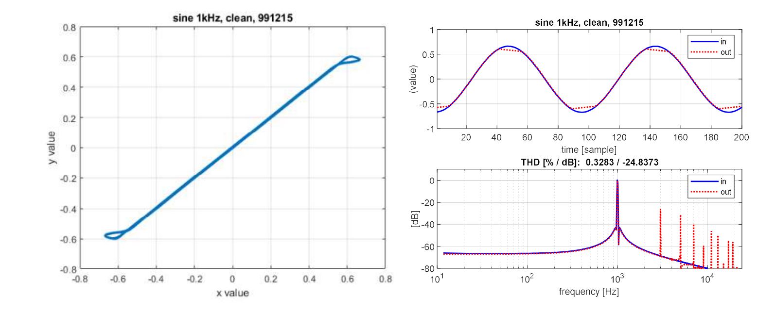
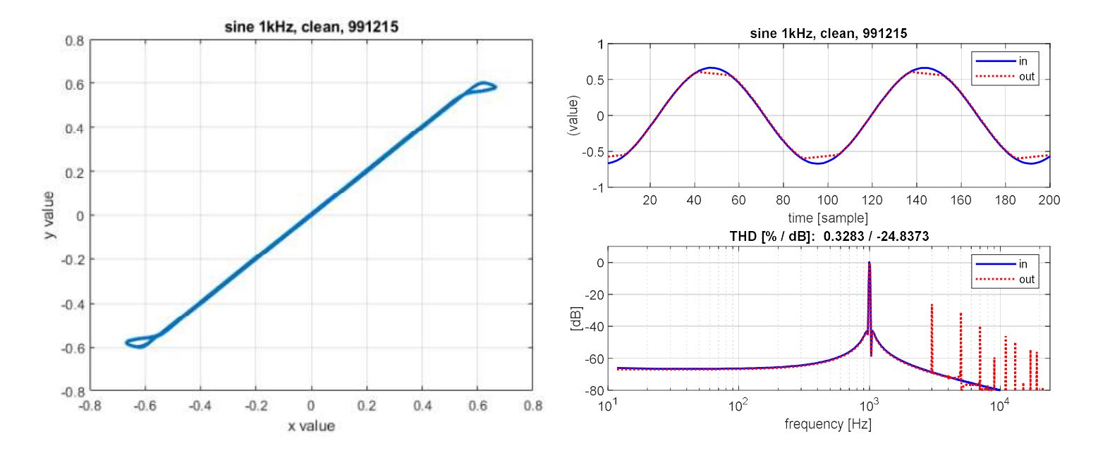
Drive1: 9 o’clock and drive2: 9 o’clock -> we leave the linear range, begin to hard clip, THD=0.33%
 |
Drive1: 12 o’clock and drive 2: 7 o’clock -> hard clipping (note the hysteresis), THD=17.4%
 |
Tube Drive
Drive1: 7 o’clock and drive 2: 7 o’clock -> distortion (simulate Marshall), THD=1.95%
 |
Drive1: 12 o’clock and drive 2: 7 o’clock -> distortion (simulate Marshall), THD=5.9%
 |
Drive1: 7 o’clock and drive 2: 12 o’clock -> distortion (simulate Marshall), THD=7.5%
 |
Drive1: 12 o’clock and drive 2: 12 o’clock -> distortion (simulate Marshall), THD=8.5%
 |
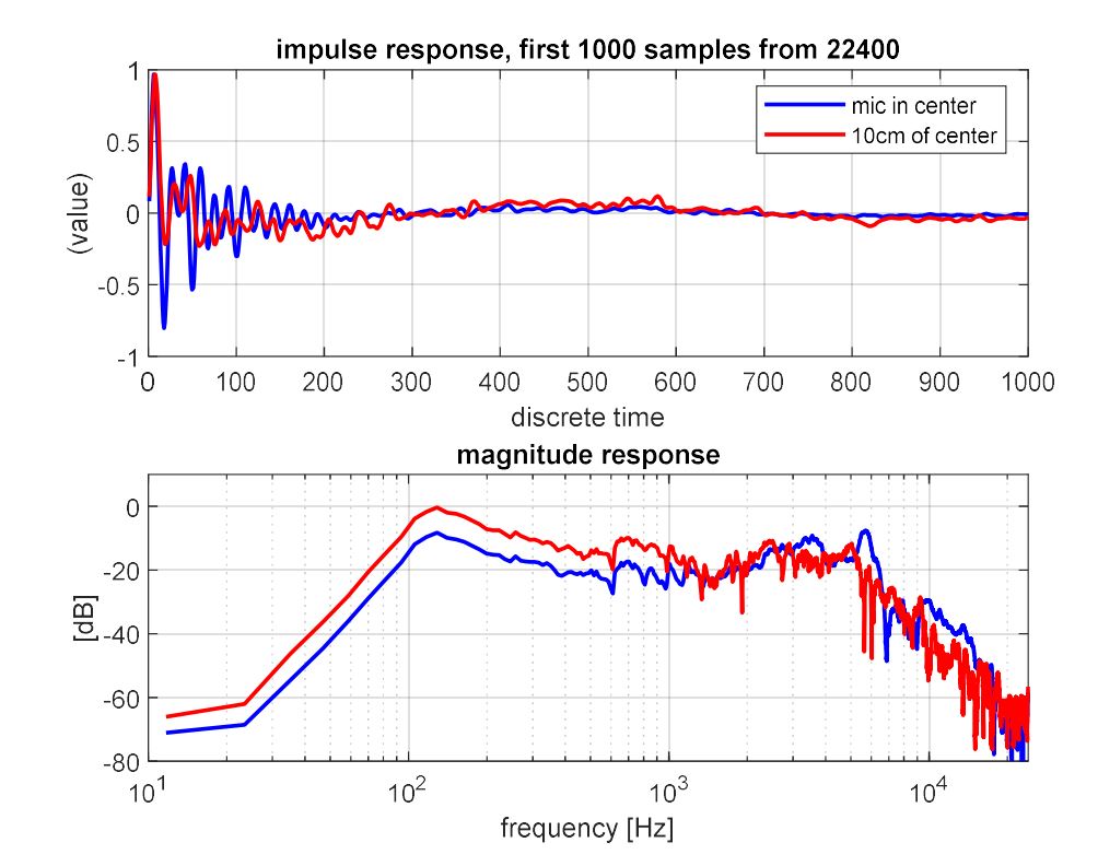
We conclude the chapter showing an example of a separate speaker cabinet simulation. It is assumed that the speaker cabinet behaves as a linear system and therefore can be modelled with a linear filter. The impulse response between the electric input to the speakers and the electric output of a microphone positioned in front of the speaker cabinet is measured. For these measurements the microphone is usually placed close the grill of the speaker cabinet.
 For example, there exists a ‘free to use’ resource of about 200 different speaker cabinet impulse responses (link). (‘All files are copyright - created by Noah Beamer/Aegean Music - Permission is hereby granted to use these files for processing audio. You may not distribute these files, even modified versions, without the creator's consent.’)
These 200 impulse responses belong to a classic Marshall 4x12 speaker cabinet (with 4 times 12 inch speakers). The high number of variations arises from different distances, angles and two types of microphones. We show 2 examples of this data base measured with a microphone Shure SM57 about 4cm in front of the speaker grill.
We did prepare an Audio Sheet to acoustically demonstrate this digital guitar distortion with and without separate speaker cabinet simulation. An additional Exercise Sheet for this topic is available. This way you may ‘work’ as an artist or a sound engineer and create your own guitar sound.
Klaus Linhard
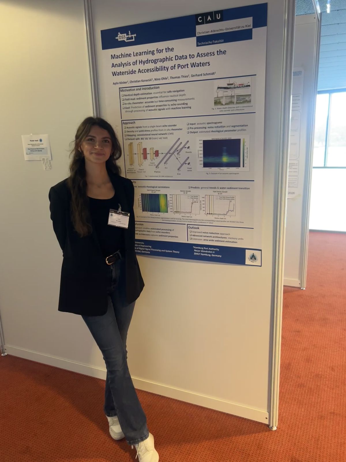 In March 2026, the DSS Chair attended the annual DAGA conference in Dresden. Thanks to the support of the GaS-Club, the student Aylin Kösker was given the opportunity to accompany the chair and participate in the conference from March 23rd to March 26th. As part of the daily poster sessions, she presented the results of her bachelor’s thesis “Machine Learning for the Analysis of Hydrographic Data to Assess the Waterside Accessibility of Port Waters” in the field of Underwater Acoustics. The thesis forms an important basis for an ongoing university research project on the acoustic analysis of sediment properties in harbor areas. The poster session enabled valuable discussions with researchers and conference participants from related research fields.